
Automotive glass replacement specialists and fleet mechanics frequently face rear window defogger failures. When cargo hits the back glass, electrical tabs rip away from printed heating busbars, or scratched conductive grid lines leave wide bands of frosted glass. Executing a successful rear window defroster repair requires specialized electrical and chemical knowledge.
Attempting to resolder a snapped copper terminal directly onto glass with a conventional soldering iron causes localized thermal shock, instantly shattering tempered rear windscreens. Instead, certified workshops deploy an engineered conductive adhesive for defroster tab bonding.
This standard engineering guide delivers definitive protocols for repairing detached defroster tabs and scratched conductive grid lines. We evaluate silver-filled conductive epoxies, low-temperature indium soldering limits, electrical multimeter diagnostic procedures, and masking templates. Auto glass professionals and collision shops will learn how to restore factory heating conductivity without risking sudden glass fracture.
Executive Summary: Defroster Grid & Tab Engineering Protocols
- Thermal Shock Hazard: Soldering irons operating at 350°C cause localized thermal stress, shattering fully tempered rear window glass within seconds.
- Silver-Filled Epoxy Superiority: Two-component silver-loaded epoxies provide both mechanical lap shear strength and low volume resistivity (< 0.001 Ω·cm) without heat.
- Grid Line Paint vs. Tab Epoxy: Single-component conductive acrylic paint works exclusively for hairline grid scratches; it lacks structural peel strength to support heavy copper wiring harnesses.
- Multimeter Diagnostic Protocol: Placing multimeter probes along a powered grid line reveals hairline breaks via sharp 12V-to-0V electrical voltage drops.
Electrical Principles: Screen-Printed Silver Ceramic Busbar Physics
During a defroster grid repair, technicians encounter screen-printed metallic tracks. Understanding electrical resistance heating explains why correct conductive materials are vital.
Joule Heating and Grid Circuit Design
Rear window defrosters operate on Joule heating principles (P = V2 / R). Automotive glass manufacturers screen-print ceramic silver-frit paste onto flat float glass before heating it in tempering furnaces.
The silver paste vitrifies into the ceramic enamel at 650°C. Parallel grid lines draw approximately 10 to 20 amperes of current from a 12V electrical system, dissipating sufficient thermal wattage to melt frost and evaporate condensation.
The Lethal Risk of High-Heat Soldering
Automotive rear windows are manufactured from single-sheet tempered glass, possessing high internal compressive surface stress. Touching a 350°C soldering iron to cold glass creates a steep localized thermal gradient.
This thermal expansion ruptures the tempered compressive boundary layer, detonating the entire windscreen into thousands of tiny dull cubes. Consequently, cold-curing conductive chemical bonding represents the sole safe repair approach.
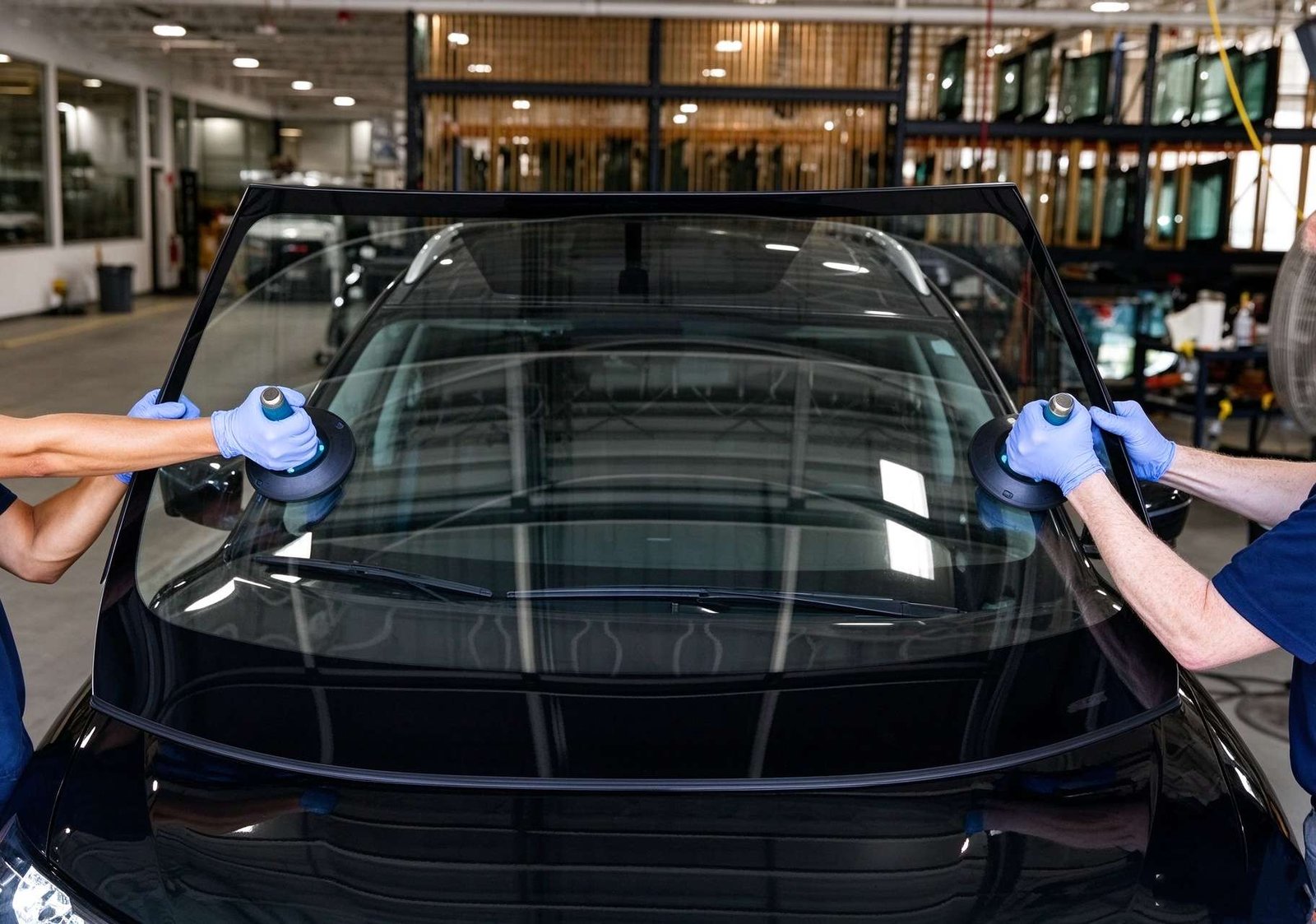
Repair Material Matrix: Conductive Epoxies vs. Grid Paint vs. Soldering
The engineering matrix below outlines performance parameters across defroster electrical repair compounds.
| Repair System | Mechanical Peel Strength | Electrical Volume Resistivity | Best Application Scope |
|---|---|---|---|
| Two-Part Conductive Silver Epoxy | High (12 to 16 MPa lap shear) | < 0.001 Ω·cm (Optimal) | Reattaching main power copper tabs to busbars |
| Air-Drying Silver Grid Paint | Negligible (Zero tensile strength) | 0.01 to 0.05 Ω·cm | Bridging hairline scratched grid lines |
| Indium-Bearing Low-Temp Solder | Moderate (8 to 11 MPa) | < 0.0001 Ω·cm | Specialized bench soldering with heat sinks |
| Standard Hardware Superglue | Brittle under vibration | Infinite (Electrical Insulator) | Unusable (Completely blocks current flow) |
Typical Application Scenarios: Workshop Realities & Defroster Failures
Reviewing common workshop repair challenges demonstrates how proper electrical diagnostics prevent unnecessary full rear glass replacement.
Scenario A: Heavy Cargo Snapped Power Busbar Terminal
An SUV owner loaded mountain bicycles into the rear cargo compartment, catching a handlebar on the defroster power lead. The impact ripped the copper terminal tab cleanly off the driver-side rear quarter busbar.
The dealership quoted $1,200 for full rear glass replacement. Instead, an independent auto glass technician cleaned the silver busbar with isopropanol, mixed a 1:1 ratio of conductive silver epoxy defroster compound, and clamped the copper tab with masking tape for 24 hours. The repair restored full 14-amp current flow at a fraction of replacement costs.
Scenario B: Tint Removal Scratches on Horizontal Heating Grid Lines
A detailing shop stripped aged purple window tint from a sedan using an aggressive razor blade, severing three horizontal heating lines across the center view.
During cold mornings, three wide bands of fog obstructed rear visibility. Technicians located each micro-scratch with a digital multimeter. By applying automotive masking tape along the grid contours and painting two thin layers of conductive silver grid resin, the lines were bridged seamlessly.
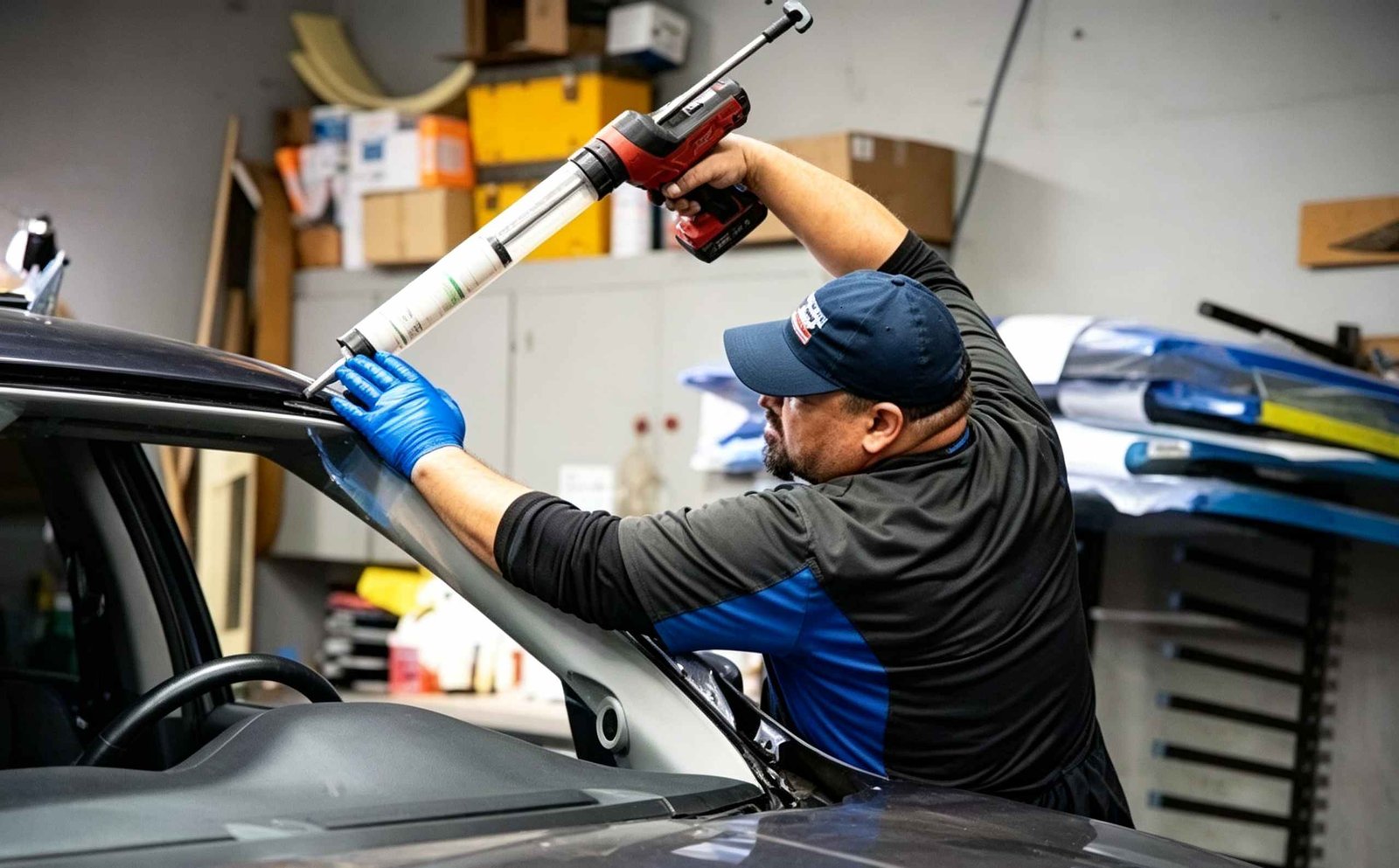
Standard Operating Procedure: Five-Stage Defroster Repair SOP
Executing this standardized procedure guarantees zero electrical resistance spikes and prevents premature tab detachment.
Step 1: Multimeter Voltage and Continuity Diagnostics
Turn on the vehicle ignition and switch on the rear defroster. Connect the negative multimeter lead to a clean vehicle chassis ground. Probe along each heating line from the positive busbar toward the negative side.
A functional line exhibits a smooth voltage taper from 12V down to 0V. An abrupt drop from 12V to 0V pinpoint-identifies the exact physical scratch location.
Step 2: Substrate De-oxidation and Cleaning
Scrape oxidized silver-frit residue lightly using a fiberglass abrasive pencil or 600-grit sandpaper. Avoid stripping the printed track down to bare glass. Wipe thoroughly with pure isopropanol to remove dust and body oils.
Step 3: Masking Template Placement
For grid line repairs, apply two strips of low-tack automotive masking tape parallel to the damaged track, leaving a precise 1mm gap exposing the severed line. Ensure the tape edges seal tightly to avoid paint bleed.
Step 4: Conductive Resin Application
For broken lines, brush conductive silver paint across the gap in two thin coats, allowing 15 minutes between applications. For broken tabs, dispense equal parts of conductive silver epoxy, mix thoroughly for 60 seconds, and apply a 1mm droplet onto the copper tab base.
Step 5: Clamping and Cure Time Protocol
Press the copper tab firmly onto the glass busbar. Secure with blue masking tape for at least 4 hours at 20°C. Allow a full 24-hour cure window before reconnecting the female wire spade terminal or switching on electrical current.
Engineer’s Technical Trade-Offs: Boundaries of Defroster Repair
Professional auto glass technicians must understand where chemical repair kits succeed and where replacement is unavoidable.
- Grid Severance Limits: Chemical silver paint effectively repairs scratches under 3mm wide; wide scrapes exceeding 10mm experience high electrical resistance and overheating.
- Busbar Delamination Boundary: If the ceramic silver busbar has peeled completely off the glass substrate down to bare silica, conductive epoxy lacks an electrical path, requiring glass replacement.
- No Immediate Current Load: Energizing the defroster circuit before the conductive epoxy fully polymerizes creates resistive hot spots that instantly melt the uncured polymer matrix.
Frequently Asked Questions: Rear Defroster Repairs
Can I use a regular soldering iron to solder a defroster tab back on?
No. Never use a standard high-heat soldering iron on rear window glass. Automotive rear windows are fully tempered; touching a hot iron to the glass creates severe localized thermal shock that will instantly shatter the entire window. Only specialized low-temperature soldering tools or conductive silver epoxies should be used.
Why did my glued defroster tab smoke and melt off when I turned on the switch?
This failure occurs when using non-conductive household glue or energizing conductive epoxy before it achieves full 24-hour polymerization. Rear defrosters draw 10 to 20 amps. High electrical resistance across an improper joint creates intense resistive heat (Joule effect) that burns the adhesive immediately.
How do I test if my repaired defroster line is working properly?
Use a digital multimeter set to DC volts with the ignition and defroster switched on. Connect the negative meter lead to vehicle chassis ground, and gently touch the positive probe to the center of the repaired line. You should measure approximately 6 volts, confirming balanced electrical resistance along the circuit.
Engineering Summary: Safe Electrical Restoration and Winter Driving Visibility
Restoring broken rear defroster grids and separated power tabs is a highly cost-effective repair that protects vehicle safety. By avoiding dangerous soldering iron thermal shock, verifying voltage drops with precision multimeters, and deploying silver-filled conductive epoxies, auto glass technicians deliver factory-grade electrical continuity that withstands harsh winter freezing conditions.
Authored by ChemPU Automotive Application Engineering Team
Specializing in OEM direct-glazing polyurethane formulation, crash-retention validation per FMVSS 212 standards, and high-performance structural elastomeric bonding solutions for global automotive manufacturers.
Quality Certification: ISO 9001 / IATF 16949 Certified Adhesive Manufacturing
Source Professional Automotive Adhesives & Glass Repair Systems
Partner with ChemPU, an ISO 9001 and IATF 16949 certified Chinese manufacturer. We provide high-performance polyurethane direct glazing adhesives, conductive repair compounds, and private label cartridges for international distributors and fleet repair networks.
Direct WhatsApp Technical Inquiry: +86 15216655520

